Two constructions
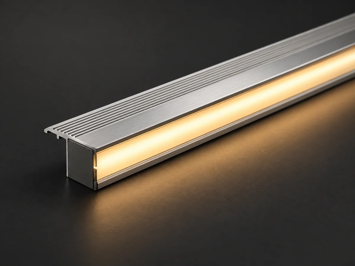
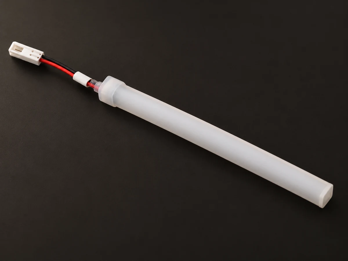
Choose a profile with diffuser or a side-emitting silicone strip to suit the tread and mounting surface.
Product category
Aluminium-profile and side-emitting silicone strips, selected for the step size, color temperature and driver.
Content previewProduct information and specifications are selection drafts. Confirm the model before ordering.
Step lighting
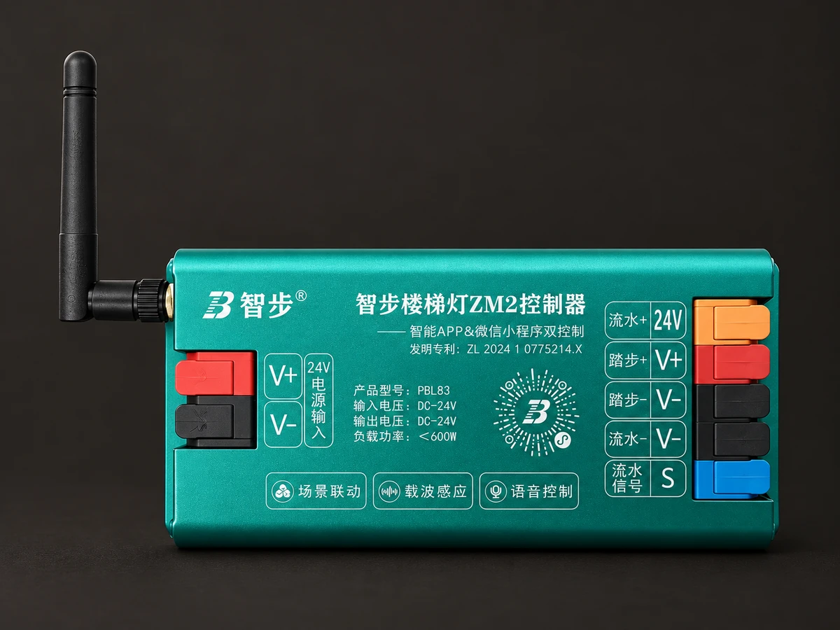
Choose a 10 × 10 mm aluminium profile or a 12 × 12 mm side-emitting silicone strip, cut to the measured length of each tread. Single-CCT, three-wire dual-CCT and two-wire dual-CCT versions use different modules. Match the strip, driver, main harness and controller as a system. The photograph shows the end, leads and connector of a silicone strip.
Choose a profile with diffuser or a side-emitting silicone strip to suit the tread and mounting surface.
Single-CCT options are 3000, 3500 and 4000 K. Dual-CCT options have separate two-wire and three-wire series.
The PBL802 family serves single-CCT strips; PBL803 and PBL808 families use different dual-CCT connections.
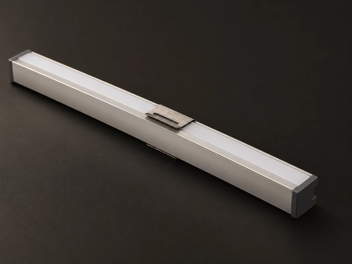
The profile, diffuser and mounting clip form the strip housing. Check the recess and mounting surface before installation.
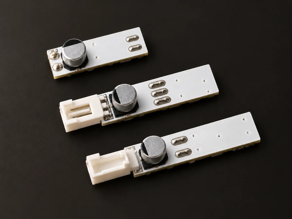
Distinguish single-CCT and dual-CCT modules. Match the strip wiring, terminals and controller.
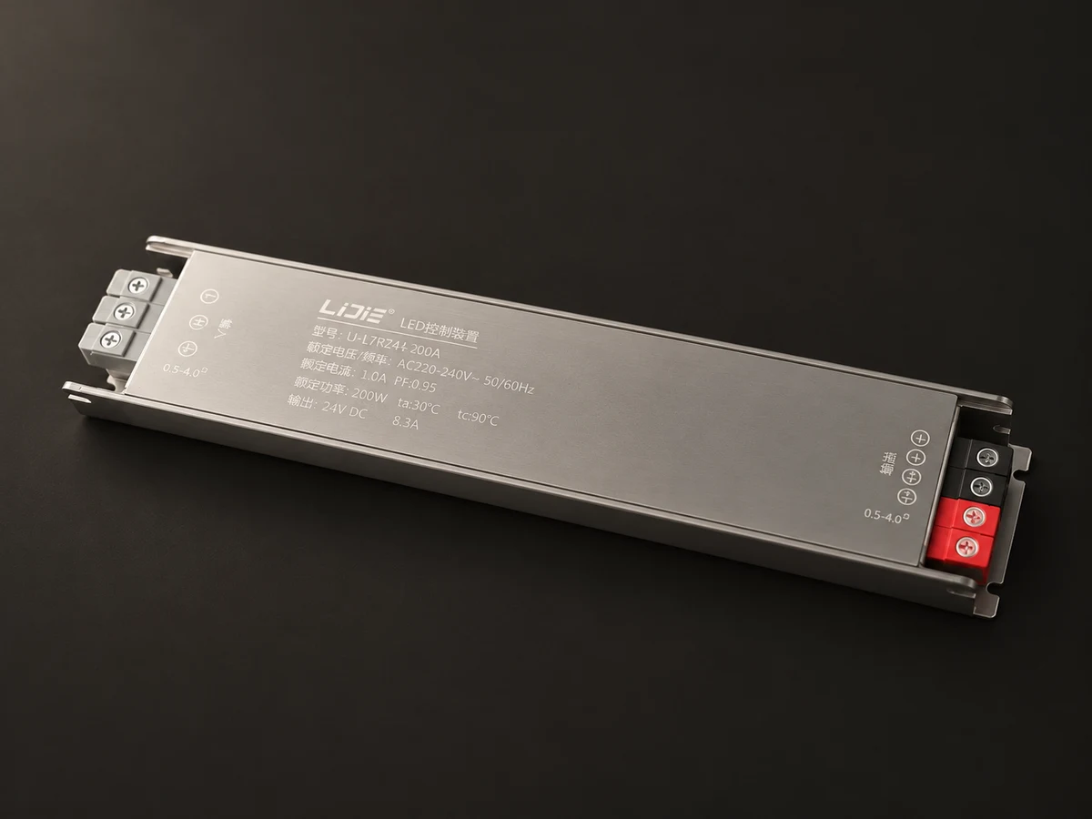
Size the supply for the complete load. Check the actual model, output voltage and ventilation requirements.
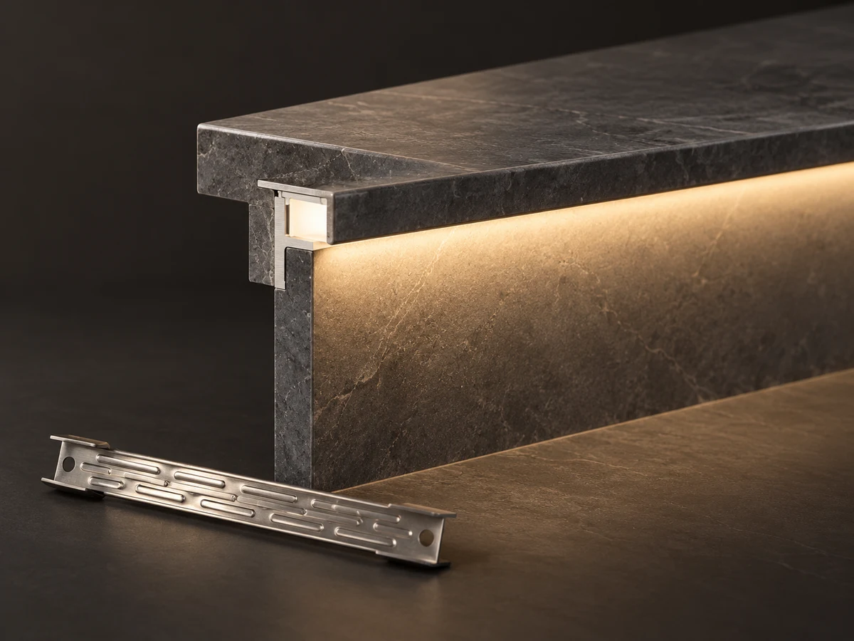
Plan the recess and retaining clips. This illustration does not replace model-specific dimensions or installation instructions.
Specifications & selection
Check these conditions for your installation and intended use.
Measure each tread, choose the construction, then select single-CCT, three-wire or two-wire dual-CCT.
Distinguish bare and terminal-equipped modules. A module rating of 24 V, 30 W MAX is not the capacity of the complete system.
The source gives a 15 × 15 mm recess reference. Check it against the selected profile, finish and fixing method.
Documented values · Review pending
Model-specific values from the 2026-10-21 product supplement, pending product review. Confirm the PBL808 CCT range and module/controller compatibility. Recess and cutting guidance applies only to the matching construction.
Installation planning
Record the site conditions, then use the selected model’s instructions to plan installation and wiring.
Measure each tread and count the steps before choosing a 10 × 10 mm aluminium profile or 12 × 12 mm silicone strip.
Check recesses and fixings for the selected construction. The source gives a 15 × 15 mm reference recess and a 12 cm clip.
Disconnect power and follow the matching instructions. Separate the diffuser and move the strip clear before cutting the aluminium. Cut the strip only at confirmed marks; never saw through the assembled strip.
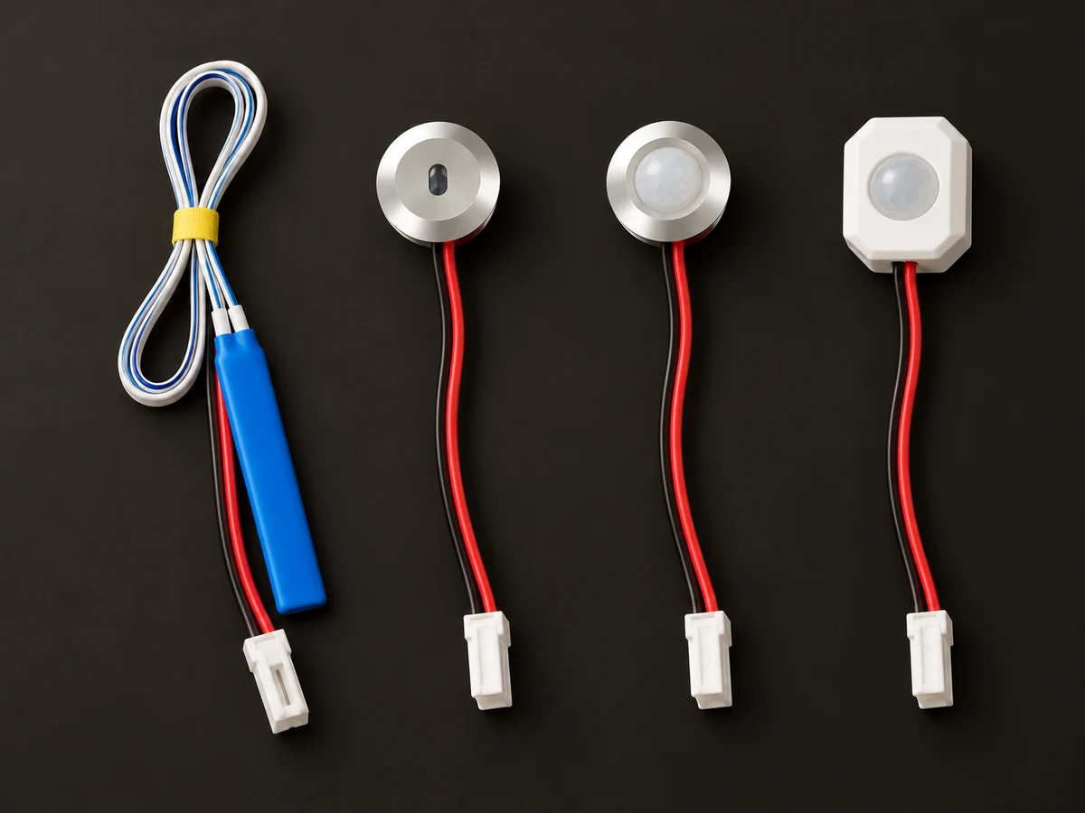
Match modules, wiring, terminals, controller and supply capacity; trial-fit each section and test sensing in both directions before fixing.
Check power, interfaces and compatibility for the selected models.
Share the installation location, dimensions and requirements so we can help with the configuration.
Enquire about this product